Tech Talks
Phase Rotation - How to determine if phase rotation is set correctly
The phase rotation setting in a relay can be set to either ABC or ACB. This setting allows the relay to determine if the motor is running in the forward or reverse direction. This is important to prevent damage to a motor and is used in multiple settings such as current unbalance, phase reversal, and negative sequence overcurrent to trip the motor when reverse phase rotation is detected. Phase rotation is also used for metering purposes.
If the motor is spinning the forward direction in the field, the relay phase rotation needs to be verified. If the motor is spinning in reverse in the field, then when the motor wiring is corrected, the same wiring correction needs to be done to the relay, then the relay phase rotation needs to be verified. The following methods will help to determine the correct phase rotation of the motor. Once the correct phase rotation of the motor is determined, the phase rotation relay setting can be set to match.
*The following methods use pictures from a GE869 relay.
Method #1
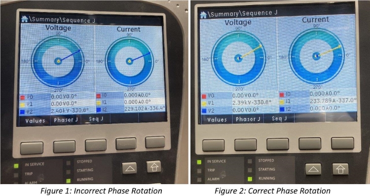
- The GE869 relay has a ‘Sequence J’ screen. On this screen values are shown for both voltage and current for:
- V0/I0 – zero sequence voltage/current (Ground current)
- V1/I1 – positive sequence voltage/current (Normal operation)
- V2/I2 – negative sequence voltage/current (Incorrect phase rotation)
- See Figure 1 below, both voltage and current values are in the V2/I2 negative sequence row. Since the motor has been determined to be spinning in the forward direction in the field, the phase rotation in the relay needs to be changed from either ABC > ACB or from ACB > ABC.
- In this example the phase rotation was changed from ABC > ACB and in Figure 2 below both the voltage and current values are now in the V1/I1 positive sequence row.
Method #2
- This method uses the angle of the phasors to determine the correct phase rotation. See Figures 3 and 4 below, the phasor diagrams are the same whether the relay is set to ABC or ACB.
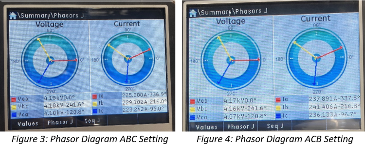
- To determine the correct phase rotation using the phasor diagrams you need to know that all phasors rotate counterclockwise. This is shown by the arrows in Figure 5 below.

- Knowing that the phasors are rotating in a counterclockwise direction we can now determine the phase rotation of the motor. We can use the 0° on the right side of the phasor diagram as a reference. Each time a phasor crosses the 0° point while rotating counterclockwise represents the phase order of the motor.
- Since the two options for phase rotation are ABC and ACB you always want to start with A phase. In this case A phase (the red arrow) is already at the 0° reference point for both voltage and current. When the phasors rotate counterclockwise, the next phasor to reach the 0° point (in most cases every 120°) is the next phase in the sequence. In this case the blue phasor, C phase, is the next phasor to cross the 0° marker. At this point the phase rotation has been determined to be A-C and by default the last phase is B. So, the phase rotation is A-C-B.
Method #3
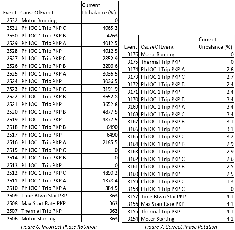
- Current unbalance is the measure of how much negative sequence current is detected in the operation of the motor. Current unbalance is a measurement from 0% to 100%.
- If the current unbalance is ever detected at values greater than 100%, this can be a sign that the phase rotation is set incorrectly in the relay.
- The current unbalance values should be recorded in the event log of the relay.
- In Figure 6 below, current unbalance values on a motor start event range from 363% - 4890.2%. This is a clear indication of incorrect phase rotation. The phase rotation was changed in the relay and the resulting start event can be seen in Figure 7 with current unbalance values ranging from 1.3% - 4.1%.
Method #4
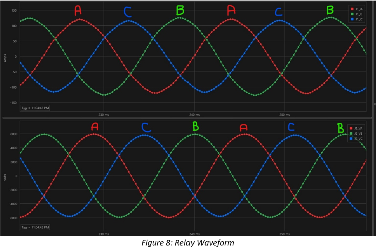
- Waveform captures can obtained from relay event files. Figure 8 below shows current on the top and voltage on the bottom. The phase rotation can be determined by picking a part of the waveform (peak, zero crossing, or bottom) and seeing which order the phases appear.
- Using the peak of the waveforms in figure 8, we start by finding a peak for phase A (red). Then the next peak is phase C (blue) followed by phase B (green). The phase rotation of the motor is determined to be ACB.
Conclusion
It should always be verified that the motor is wired correctly and is rotating in the forward direction before any settings changes are made in the relay. Once the motor is verified to be wired correctly, then any method above can be used to determine if the phase rotation setting in the relay is correct. Again, there are only two options for the phase rotation setting, ABC and ACB.
Method #2 is the most universal between different relays. This is because the phasor diagram can be viewed from most all modern relays either via the front panel or through event analysis software.